
This skinny direction set is only for the ACID distribution of app_rpt. (may be valid for other distros ?)
Using the Parallel port for radio COS / PTT is the cheapest and easiest route to go unless you want to hack-up a USB sound dongle that we will not talk about here. If you wish to do that see this link / PDF.
When using parallel port pins for any logic connections most especially experimental ones, I always suggest using something to buffer the lines in the printer/parallel port so that you do not do more damage than to just the port of your PC if higher voltage gets to one of the pins.
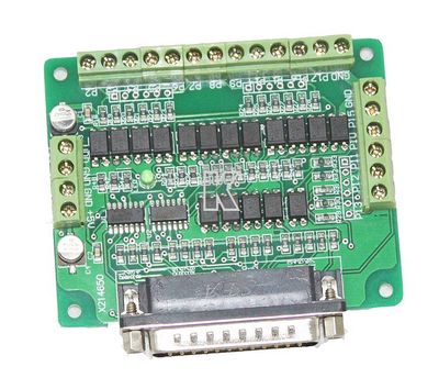
Parallel Port Breakout card with Opto-Coupled Transisters on output.
When I had built a DOS box repeater in the 90’s, I used a opto-coupled transistors to isolate the pins. Now-A-Days you can save yourself a bunch of time and money by buying parallel port cards already made with opto-couplers for cnc driving/controlling on eBay for $30 or less. They even have screw terminals for easy wiring ! The benefit I had back then is I could change the Parallel port card if I damaged it. Now they are built-in. Easy to damage more than just the port.
Just some “experience” talking here. And you know our moto definition of that word ( or see our home page )
First, you need to include a line like this for your node in RPT.CONF :
iobase = 0x378 ; Parallel port address (using for cor/ptt & switches +dh-rbi )
The address is the parallel port address in hex. Normally 378, 278, 3bc are common addresses for the 1st, 2nd and 3rd ports.
OH… for those that do not know…
PTT is for “push to talk”. A TX line that normally goes to ground when active but not all are like this.
COS/COR is “carrier operated signal” or “carrier operated relay”. The logic on this line varies widely depending on where you can get the signal in the receiver. If your radio has a “s-meter”, that would be a good area to find a appropriate signal.
A short description of the pins we use on a parallel port.
We have:
8 data output lines starting with pin 2 as output 1 (pp1) to pin 9 as output 8 (pp8). These can be used for PTT on multiple nodes as defined in usbradio.conf . I would suggest starting from Output 8 (pin 9 / pp9) and work backwards to reserve the first three for a DH-RBI-1 or future devices. You can also use these to control other devices using relays (out of scope with this page).
5 data input lines Pins 10,11,12,13 & 15 can be used for COS detections across multiple nodes. You can also use these from other sensors to trigger events in software (off topic, not going there in this page).
Changing the logic in/out with the software:
Parallel Port pins are defined in app_rpt software as “pp1”, “pp2”, “pp3″…etc
Setting them in USBRADIO.CONF
[usb29285]
pp6=ptt
pp11=cor
; carrierfrom=no ; available options for COS/COR type – Uncomment what’s needed.
; carrierfrom=dsp ; use a valid signal decoded in DSP (internal)
; carrierfrom=pp ; states we use pp for COS w/normal logic
carrierfrom=ppinvert ; this option inverts the logic for cor on the chosen pp
; carrierfrom=usb ; for hacking usb dongle method
; carrierfrom=usbinvert ; same as above but inverted
; carrierfrom=vox ; use vox for COS ( useful for a HF remote base )
ctcssfrom=dsp
rxdemod=flat
txprelim=yes
txlimonly=no
txtoctype=notone ; Transmit tone control type: no,phase,notone
; no – CTCSS tone encoding with no hang time
; phase – encode CTCSS and reverse phase AKA (“reverse burst”) before unkeying TX
; notone – encode CTCSS and stop sending tone before unkeying TX AKA (“chicken burst”)
plfilter=yes ; Filter PL tones/don’t pass to transmitter
txmixa=composite
txmixb=no
invertptt=0 ; use this to invert the normal logic state of the line
duplex=1
rxondelay=20
rxnoisefiltype=0
eeprom=0
#includeifexists custom/usbradio.conf
Some important notes:
The example above is a no-tone with carrier signal (COS) inverted. A simple set-up.
If you lack the ability to set-up a COS circuit, your best option is to set cos as tone/dsp and use that tone to signal a active receiver. Yes that makes your machine a PL’d repeater that you can not turn off the tone. But perhaps it will get you up and running for now.
You may need to invert the logic of pins manually with hardware/transistor to prevent transmitter “key-up” while booting your asterisk machine or it is powered off in certain circumstances where that initial transmitter hang would be disruptive until you get it turned on or booted.
As parallel port outputs (from PC) will only sink about 150 -250 ma of current and about 250-450 ma if you are using the opto-coupled board, you may need to use the line to toggle a external transistor or relay to achieve higher currents to switch the PTT or other devices. If in doubt, use a low current fast relay or transistor to buffer the signal. Save your port and/or machine.